Alexander Lipanov, PhD in Computer science, Softarex Technologies, Inc.
The aim of motion tracking is to detect changes in the positions of moving objects over time based on a sequence of images. Motion tracking is widely used for monitoring activity in public places as well as for detailed analysis of video sequences recorded by various video surveillance systems. This technology is also very important for scientific, technical, and medical applications, such as industrial robots, road traffic control systems, livestock RFID tags, and blood analysis.
In recent years, extensive research has been conducted in order to develop more advanced, robust, and multi-purpose
object tracking algorithms. Presently, there are three large groups of such methods:
-
Correspondence-based object tracking – these algorithms perform object detection by representing discrete
objects as centroids or silhouettes and then establishing correspondence between them frame by frame. -
Transformation-based object tracking – these algorithms perform object detection by transforming discrete
objects into planar surfaces, such as rectangles or ellipses, and estimating the changes in their relative
positions frame by frame. -
Contour-based object tracking – these algorithms perform object detection by representing discrete objects
as contours (boundaries) and matching similar contours with each other or with a predefined template contour
frame by frame.
Based on our own experience and knowledge, we suggest our own method for boundary detection – the
Integro-Differential Algorithm.
The main idea behind this approach is to combine the benefits of the three groups of algorithms mentioned above.
First of all, we need to define the average brightness in the neighborhood of the reference object’s center
C0 :
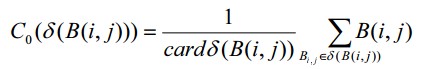
where B (i, j) is the brightness function of the image being analyzed.
The second step is to build a brightness distribution histogram based on the calculated value of C0:
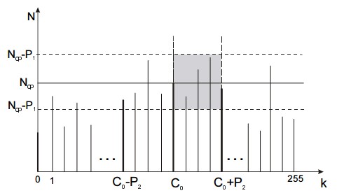
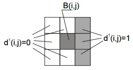
In the third step, we can define the optimal brightness threshold T:
where T0 = 0 is the initial value of the threshold,
Nk is the number of points with brightness k,
Ncp is the number of points with brightness belonging to the neighborhood of the average
brightness C0,
k is the current value of brightness,
P 1 > 0 and P 2 > 0 are the pre-defined constants for boundaries of the object’s brightness range.
Our experiments have shown that most computer vision systems deliver the best results with P1 = 64 and
P2 = 50. However, these two thresholds are always empirical and strongly depend on the type and quality of the images being analyzed.
In this step, our image comprises three subsets, which are the subset of the object’s points, the subset of object’s boundaries, and the subset of background’s points. Therefore, we need to remove (subtract) all the points belonging to the background and inner areas of the object to obtain the subset of the object’s
boundaries.
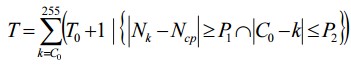
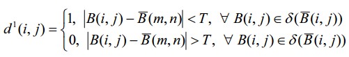
Let’s define the supplementary d 1 set in the following way:

where i and j are the width and height of the image, respectively (in points),
m and n run through 
from the beginning to the end.
In the d1 set, each element d1 (i, j) = 1 corresponds to a point of the object’s contour,
while each element d1 (i, j) = 0 stands for a point of the background, object’s inner area, or
their intersection, as shown in the picture below.
Using the d1 set, we can solve two important tasks at once: find the points of similar
brightness on the image and at the same time filter out various noises, distortions, and glitches, since their
brightness significantly differs from the brightness of the points belonging to
 .
.
Now, let’s define yet another set and name it d2:
where i and j are the width and height of the image, respectively (in points).
The d2 set contains the points with brightness close to the average brightness C0
limited by the T threshold defined above. The main difference between the d1 and d2 sets is
that the former comprises points with brightness belonging to  ,
,
while d2 consists of points with brightness between C0 – T and
C 0 + T plus all the points of the d1 set. The d2
set makes the entire algorithm more robust, accurate, and less dependent on the object type and image quality.
And the last step is to define the resulting set L containing all the points of the object’s contour:
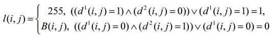
where  .
.
This expression removes all the points outside the object’s contour by assigning them 255 (i.e. white color code),
while leaving the points of the object’s contour unchanged. As a result, the L set will contain only the points of the object’s contour and thereby the task will be solved.
In general, this algorithm is relatively simple, delivers reliable results in real time, and saves computing resources, since it uses only basic arithmetical and logical operators. The latter is especially important for the entry-level workstations that often cannot provide enough processing power.